To better-understand SMM-SOI growth, it is useful to construct a basic growth model for the system. Here, basic conditions are assigned to the various interfaces of respective materials in the Al-oxide-substrate system. This system is then flooded with the deposition of Si diffusors. A model for the anticipated flux of diffusors is finally presented.
Aluminum Mediator
In the ideal case, an Al mediator film will have successfully grown as a continuous c-Al thin film in the seed areas of the silicon wafer. Over oxide regions, the Al is anticipated to form a polycrystalline thin film at room temperature and then progress as a laterally-seeded crystalline thin film. Once these conditions have been met, a model of this environment can be simplied as suggested in the following.
|
Figure 3.7. Simplified Kinetic Model of Mediator Interactions with Oxide and Substrate. The small arrows represent Al atom activity. While minimal, the activity at the oxide interface may not be negligible. At these interfaces, the Al combines with oxide to form a thin film of polycrystalline Al-oxide (e.g. alumina). |
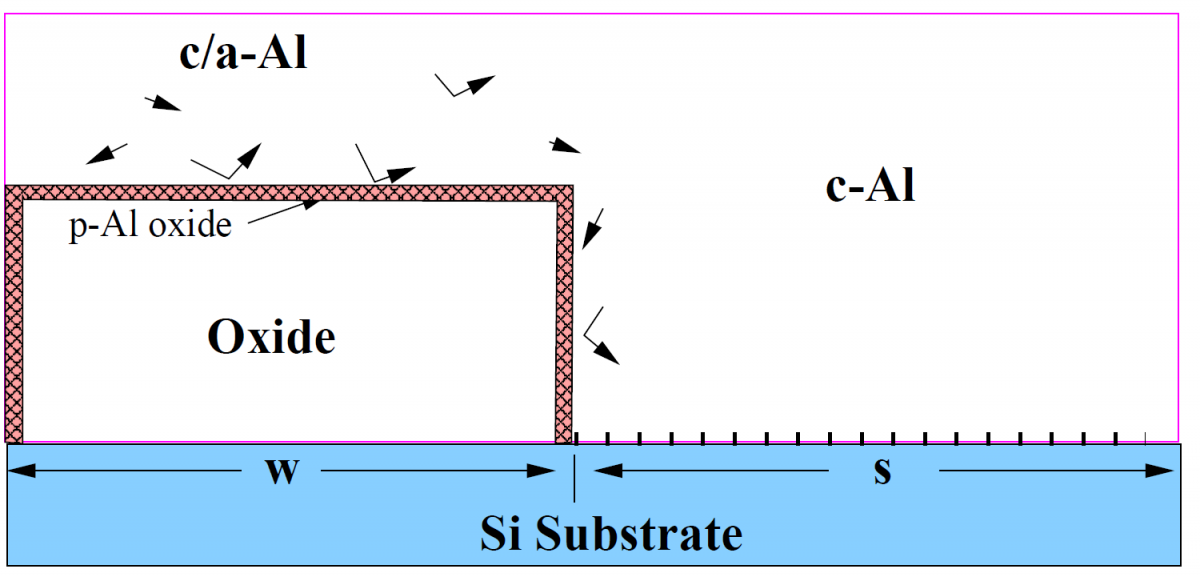
In the region over oxide, Al will combine with the oxide to form aluminum oxides (e.g. alumina) as schematically represented in Figure 3.7. This interface has been shown[1] to vary by no more than a few atomic spaces, and is therefore atomically abrupt. Above this region, Al will tend to form a polycrystalline film due to the formation of polycrystalline alumina (primarily Al2O3, or sapphire). Thus, near the oxide-Al interface there will be some movement of Al atoms as the film is deposited.
In the seed region, Al is expected to grow vertically upward in a single-crystalline manner as shown by previous SMME experiments. When the Al film thickness in this region reaches the height of the oxide step, the crystalline Al film acts as a lateral seed for the Al already present over the oxide region. As the substrate is heated, the extent to which the polycrystalline/amorphous film over oxide will crystallize due to this lateral seed is currently unknown. However, it is known that Si will diffuse through an Al film with questionable crystalline quality. Nonethless, the final Al mediator model includes the schematic representation depicted in Figure 3.7.
Silicon Diffusor
Using the Al mediator model, the material is heated to the deposition temperature for silicon ($350^\circ \textrm{C} \lt T_s \lt 500^\circ \textrm{C}$). Si diffusors enter the environment from the top of the Al film and rapidly diffuse into the mediator. In the seed region, the buried Al/Si interface readily accepts the diffused Si atoms. The buried Si film grows vertically upward in an SMME growth front (Fig. 3.8). This growth front acts as a sink for Si diffusors.
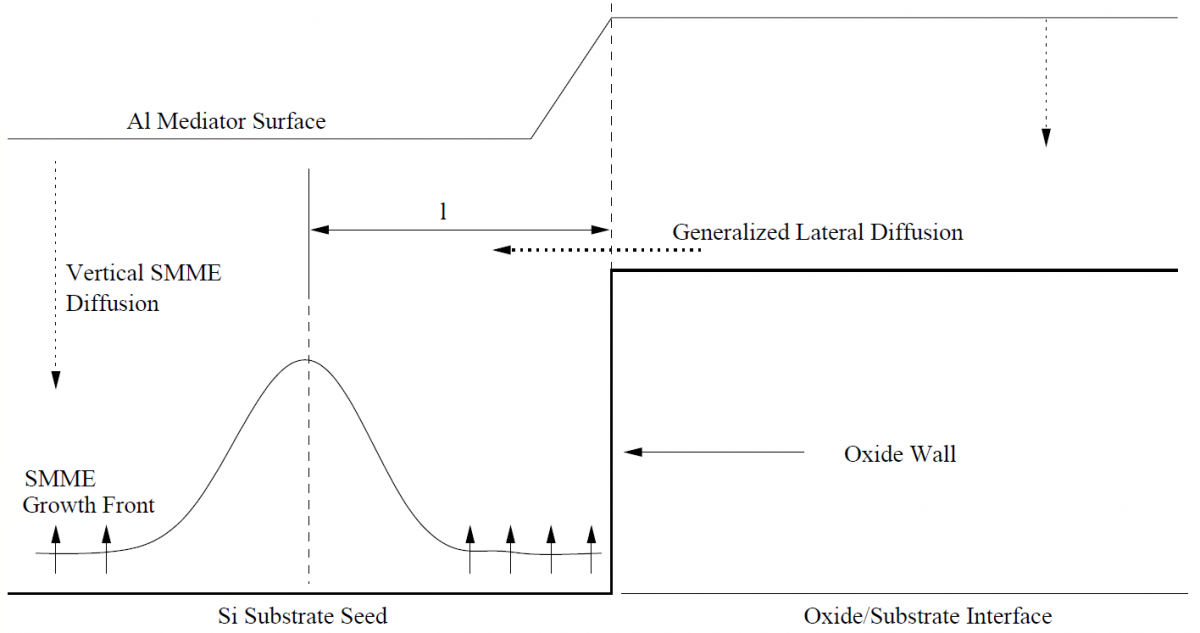
|
Figure 3.8. Proposed Kinetic Model for SMM-SOI Diffusors. Arrows represent the general direction of Si diffusors in various regions. As the region above oxide becomes saturated with Si diffusors the Si is laterally forced into the neighboring seed area where it is consumed by the SMME growth front. |
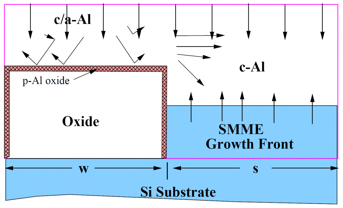
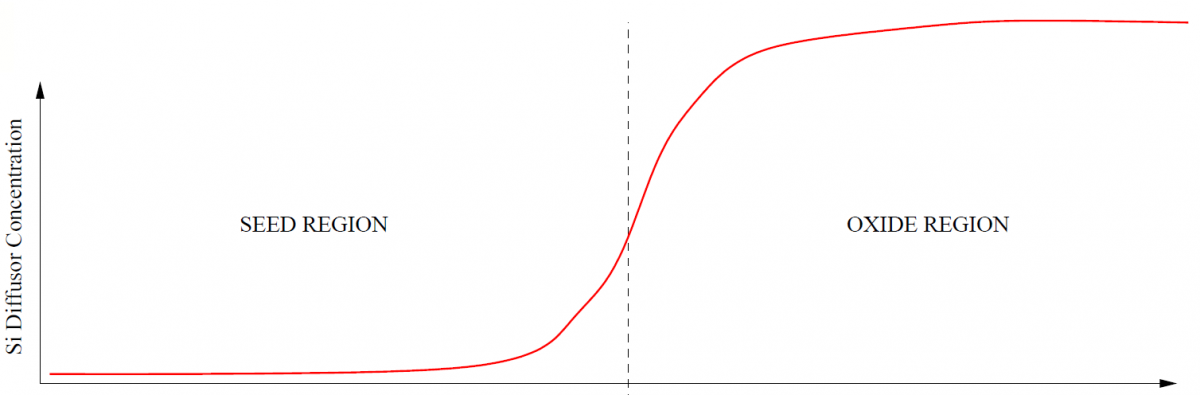
In the region over the oxide strip, Si diffusors are repelled by the polycrystalline aluminum-oxide film. Si atoms are then kinetically active in the Al mediator film, diffusing randomly throughout the film. As the deposition of Si continues, the concentration of Si diffusors over the oxide increases. This forms a concentration gradient (Fig. 3.9a) of Si atoms in the Al mediator film between the oxide region and the seed region. Therefore, the Al mediator film over oxide begins to act as a source for Si atoms. A significant dynamic contribution to the SMM-SOI system may be the lateral diffusion of Si diffusors from the oxide region into the seed region. This could initially accelerate the SMME growth front rate. This lateral flux of diffusors may cause a non-uniform growth of the front (Fig. 3.9b) in a region on the order of the diffusion length of Si in Al at the growth temperature away from the oxide wall.
The SMME growth front may be dramatically accelerated in a region a distance $\ell$ away from the oxide wall depending on the diffusor concentration gradient between oxide and seed areas. The vertical Si(111) direction may become saturated for example, and possibly result in misaligned growth defects. On the other hand, the Si(100) direction allows for much faster growth ($v_{(100)} \gg v_{(111)}$)[2] and may be preferred for large concentration gradients.
Figure 3.9. Lateral SMME Diffusion a) The concentration profile of Si atoms diffusing in the Al mediator during deposition of Si. b) Given the concentration gradient formed by Si diffusion, the oxide area becomes a source of Si atoms. The atoms are forced to diffuse laterally away from the oxide region into the seed region an average diffusion length, $\ell$. c) As mentioned in the text, despite the possibility of an accelerated growth location (an average distance, $\ell$, from the oxide wall), the SMME growth front may have enough room ($\sim 1 \mu\textrm{m}$) to successfully grow in the vertical direction and provide a horizontal seed for proper ELO. |
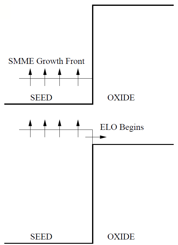
Once the vertical SMME growth front reaches the height of the oxide, lateral overgrowth begins to relax the concentration gradient as the result of a progressively diminished effective oxide area. Future investigations should confront the possible relaxation of this concentration gradient. For example, if the Si(111) direction is shown to cause defects, then a Si(110) seed might be considered (Fig. 3.10). The vertical growth front may develop appropriately. Once the vertical front reaches the height of the oxide, the fast Si(100) direction is exposed for fastest lateral overgrowth. This configuration initially accepts rapid Si diffusors in the vertical growth stage, then quickly relaxes the concentration gradient by rapid ELO.
Conversely, the Si(100) orientation can be applied along the initial vertical direction to expose the Si(110) direction to lateral growth. Both configurations should prove to help prevent the potential of defect formation in seed areas near the oxide walls. Moreover, certain ratios of effective seed areas to effective oxide areas may prove advantageous.
|
Figure 3.10. Si(110) Growth Enhancement. As an example of possible SMM-SOI growth enhancement, the Si(110) direction may be used for rapid incorporation of diffusors for fast vertical growth. Once the SMM growth front has exceeded the oxide height, the Si(100) direction is exposed for fastest possible relaxation of the diffusor concentration gradient. Likewise, a Si(100) wafer may be used for fastest vertical growth, allowing Si(110) exposure for rapid gradient relaxation. |

The concentration gradient is directly proportional to the ratio of the effective seed area to the oxide area. For example, if the two areas are laterally equal in length, the seed area may experience up to twice the flux of diffusors it would otherwise experience (as in the basic SMME, or non-oxide-patterned, case).
Despite projected obstacles concerning a saturated SMME growth front, rapid lateral Si overgrowth may still remain unaffected. Consider Fig. 3.9c. The average root mean square diffusion rate of Si in Al at $400^\circ \textrm{C}$ is $\sim 1.3 \mu\textrm{m/s}$. On top of the wall, Si diffusors are laterally diffused from the oxide region to the seed region due to a heightened diffusor concentration gradient across the oxide wall (Fig. 3.9a). At $400^\circ \textrm{C}$, Si will travel a statistical average length of $\sim 1.3 \mu\textrm{m}$ from the oxide wall. Therefore, the greatest concentration of Si diffusors will be located $\sim 1.3 \mu\textrm{m}$ from the oxide wall. The $1.3 \mu\textrm{m}$ space between this highly saturated location and the oxide wall may be sufficient space for proper vertical SMME growth (Fig. 3.9d) that may still provide a defect-free seed for epitaxial lateral overgrowth. As lateral overgrowth proceeds, the effective concentration gradient is likewise relaxed due to the diminishing effective area of the oxide region.
References
- , “Structure of the Al/Al2O3 interface”, Appl. Phys. Lett., vol. 46, 1985.
- , “Solid Phase Epitaxial Growth of Si Through Al Film”, Proceedings of the Symposium on Thin Film Phenomena Interfaces and Interactions, vol. 78. p. 293, 1978.