SEM micrographs and optical images were acquired to investigate the surface morphology of several substrates. Fig. 5.14 provides a broad optical overview of Al island formation on oxide during the SMM-SOI process. Fig. 5.15 is an SEM study of the same 10/10 $\mu$m region (cf. Fig. 4.2) studied in Fig. 5.14. Such studies exploit the cross-patterned nature of the Si and Al deposition areas (Fig. 5.16) formed by virtue of the sample heater/holder assembly geometry shown in section 4.5.
|
||||||
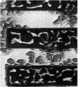
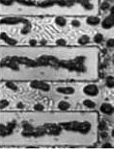
| Figure 5.14. Optical Mosaic from 10/10 $\mu$m Region (cf. Fig. 4.2). a), b) Complete Al coverage on oxide-patterned region. Here the Al appears bright, the oxide very dark. c) Transition of partial Si and complete Al coverage. d), e) Complete coverage of SMME-Si and Al. The progressive changes from region to region hint at the diffusive behavior of Si in Al during the SMM-SOI process and help to form a broad picture of the dynamic environment. Compare with Fig. 5.16 for a schematic representation of this optical mosaic and Fig. 5.15 for its SEM-interrogated equivalent. | ||||||
|
||||
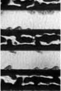
| Figure 5.15. SEM Mosaic of 10/10 $\mu$m Region (cf. Fig. 4.2). a) Complete Al-coverage on oxide pattern. b) Transitional region between complete Al-coverage and partial SMME-Si coverage. Note: The location of this micrograph on the sample is closer to region 3 (Fig. 5.16) than the optical image in Fig. 5.14c. c) Complete SMME-Si and Al coverage. This mosaic demonstrates the transformation of Al-island features (brightest features) during Si diffusion. The Al film in the seed area begins to separate from the oxide walls in (a). The Al film has already formed elongated islands on the oxide regions. In (b), the Al film has further-separated from the oxide walls in a uniform manner. Damage is already observed on Al islands on oxide, with the beginning of Si diffusion. The elongated islands begin to converge to the center of the oxide strip. Finally, at its extent in c) the Al film in the seed area has uniformly segregated into small islands along the length of each side of the seed area. Al islands on oxide have been aligned along the center of the oxide strips. Compare with Figs. 5.16 and 5.14. | ||||
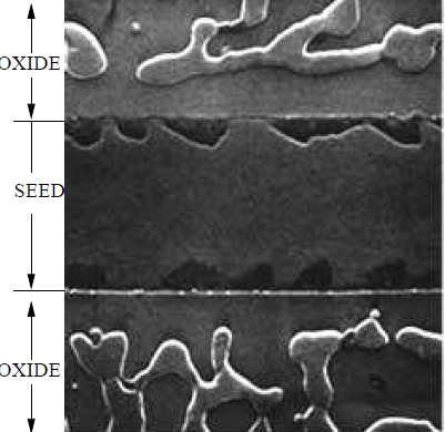
The Al-only region (Figs. 5.14a,b and 5.15a) shows the film beginning to separate from the oxide walls. In the optical image (Fig. 5.14a,b), the Al film is bright. The underlying Si substrate is dark. In the SEM image (Fig. 5.15a), the Al film is somewhat brighter than the underlying Si substrate due to the availability of free electrons in the metal Al film. On the oxide region, the bright Al is shown to readily conglomerate into elongated islands along the length of the oxide edges.
|
|||||
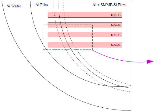
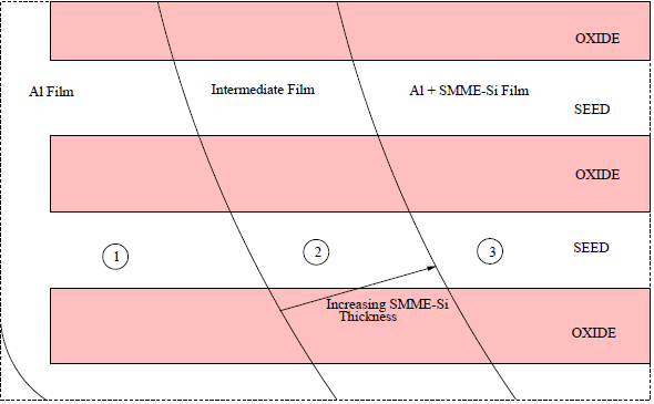
| Figure 5.16. Schematic of 10/10 $\mu$m SOI Investigation (cf. Figs. 5.14 and 5.15). a) Overview schematic of 10/10 $\mu$m oxide pattern region (cf. Fig. 4.2) depicting the cross-pattern of Si and Al deposition areas (Fig. 4.7). b) Enlarged view. 1) A region of only Al coverage over oxide patterns (cf. Figs. 5.14a,b and 5.15a). 2) An intermediate region between only-Al and Al + SMME-Si regions (cf. Figs. 5.14c and 5.15b). The arrow depicts increasing SMME-Si thickness. 3) An SMM-SOI region with Al + SMME-Si on oxide patterns (cf. Figs. 5.14 and 5.15c). | |||||
In Figure 5-14c, the Al film in the seed area continues to separate from the oxide walls, and the elongated Al islands on oxide begin to align lengthwise along the center of the oxide patterns. Both the Al film in the seed area and Al islands on oxide begin to show considerable damage produced by the diffusion of Si.
During silicon deposition (Figs. 5.14d,e and 5.15c), the Al film in the seeding area transforms into elongated islands near the edge of the oxide walls on either side of the seed area and finally separates into small islands of Al along the the oxide walls. On oxide, the elongated Al islands continue to become aligned along the center of the oxide strips and are damaged during Si diffusion. The severity of the damage is evident in the darkening of the Al islands in the optical image and the roughness of the SEM micrograph.
|
|
|
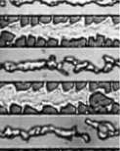
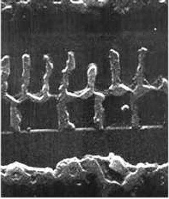
| Figure 5.17. SEM of 50/500 $\mu$m Region. Al island formations on the oxide region behave in such a manner as to peal away from the oxide edges and uniformly distribute across the entirety of the oxide surface. Small contaminants on the oxide (lower inset) promote Al film separation. As well, small Al islands are present along the nearby seed region (upper inset). |
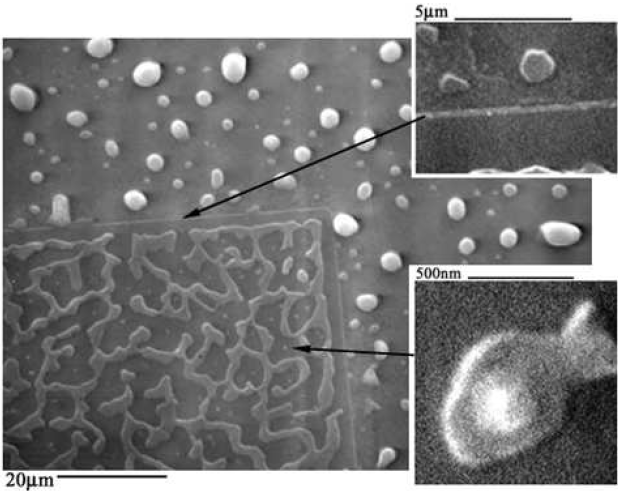
Cross-sectional SEM (Fig. 5.9) of the 2/2 $\mu$m oxide pattern shows a considerable length of the oxide pattern covered with a smooth film of Si. On the 10/10 $\mu$m pattern examined in Figures. 5.14 and 5.15, the 2/5 $\mu$m region in Figure 5.18, the 5/10 $\mu$m region in Figure 5.19, and the 50/500 $\mu$m region of Figure 5.17, along the edge of the oxide, there are smooth regions of a few microns along the entire length of the oxide strip. This oxide-long phenomenon may be explained as a separation of the Al film from the oxide edge. This separation occurred prior to Si deposition, however, as shown by the 50/50 $\mu$m region of Figure 5.17, the Al film over oxide is separated by the presence of small contaminants. Overall, all oxide patterns demonstrate similar Al film characteristics in the oxide regions.
|
|
|
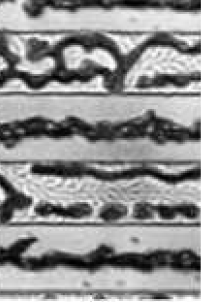
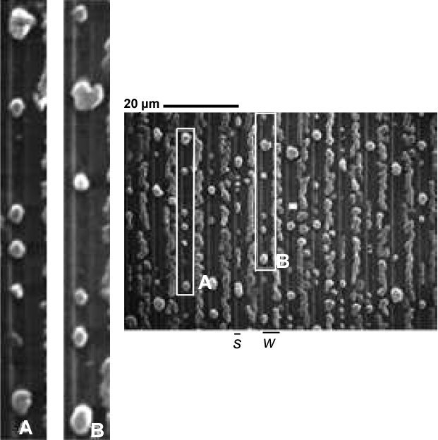
| Figure 5.18. SEM from 2/5 $\mu$m Region (cf. Fig. 4.2). A and B are two "tracks" of seeding areas that demonstrate the globular structure of Al islands. Over oxide areas, the Al islands are elongated and centered on the oxide strip as shown on the 10/10 $\mu$m SEM image of Figure 5.15 from the same sample. |
In the optical/SEM study of the 10/10 $\mu$m region in Figsures 5.14 and 5.15, Al islands are found to be two separate chains along both sides of the oxide pattern. These two chains coalesce into a single chain of islands along the center of the oxide strip as Si is deposited. An explanation for this is the advancement of the SMME growth front laterally over the oxide that may push Al islands toward the center of the oxide strip.
|
|
|
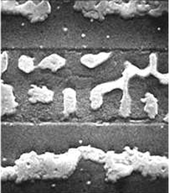
| Figure 5.19. SEM from 5/10 $\mu$m Region (cf. Fig. 4.2). "Tracks" A and B demonstrate globular Al islands in the seed area of the 5/10 $\mu$m region of the same sample explored in this section. Regions shown in insets C, D, E, F, and G show areas with congregations of small, uniformly-spaced Al islands on either side of the seed area. |
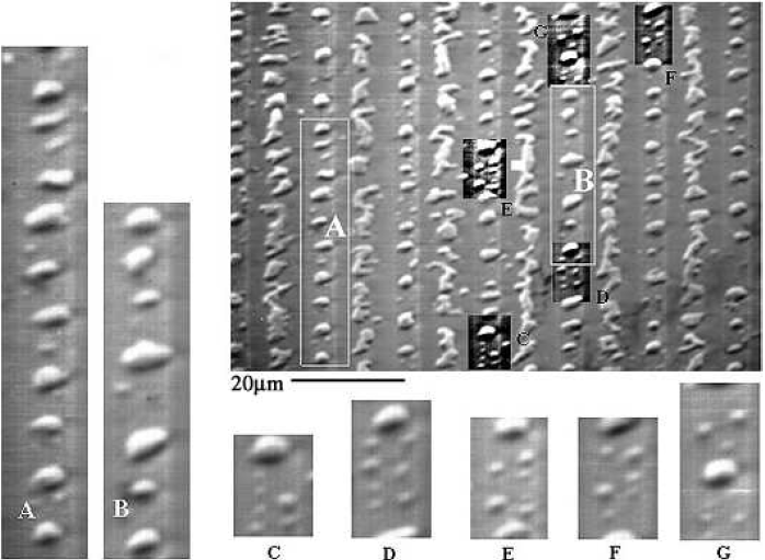
In the seed regions, a similar formation of Al island patterns is evident on all oxide patterned regions. Typically, small Al islands form 1-2 $\mu$m(cf. insets C-G of Fig. 5.19) and larger Al islands appear $\gt2\mu$m, from the oxide walls. The size and location of these islands may be attributed to the nucleation of the Al film, having been strongly affected by the diffusion of Si. Note that the Al film by itself(Fig. 5.15a), that has undergone the same stages of annealing as the rest of the sample, remains intact aside from the separation of the film from the oxide walls. This suggests that native oxides in the seed regions do not necessarily initiate the formation of Al islands, but that the diffusion of Si provides a mechanism that exploits the Al film separation from oxide walls, causing the Al film to nucleate into the observed islands. These distinct Al island sizes, shapes, and locations represent an interesting phenomenon that may be unique to the SMM-SOI process and merit further investigation.